贴图分析
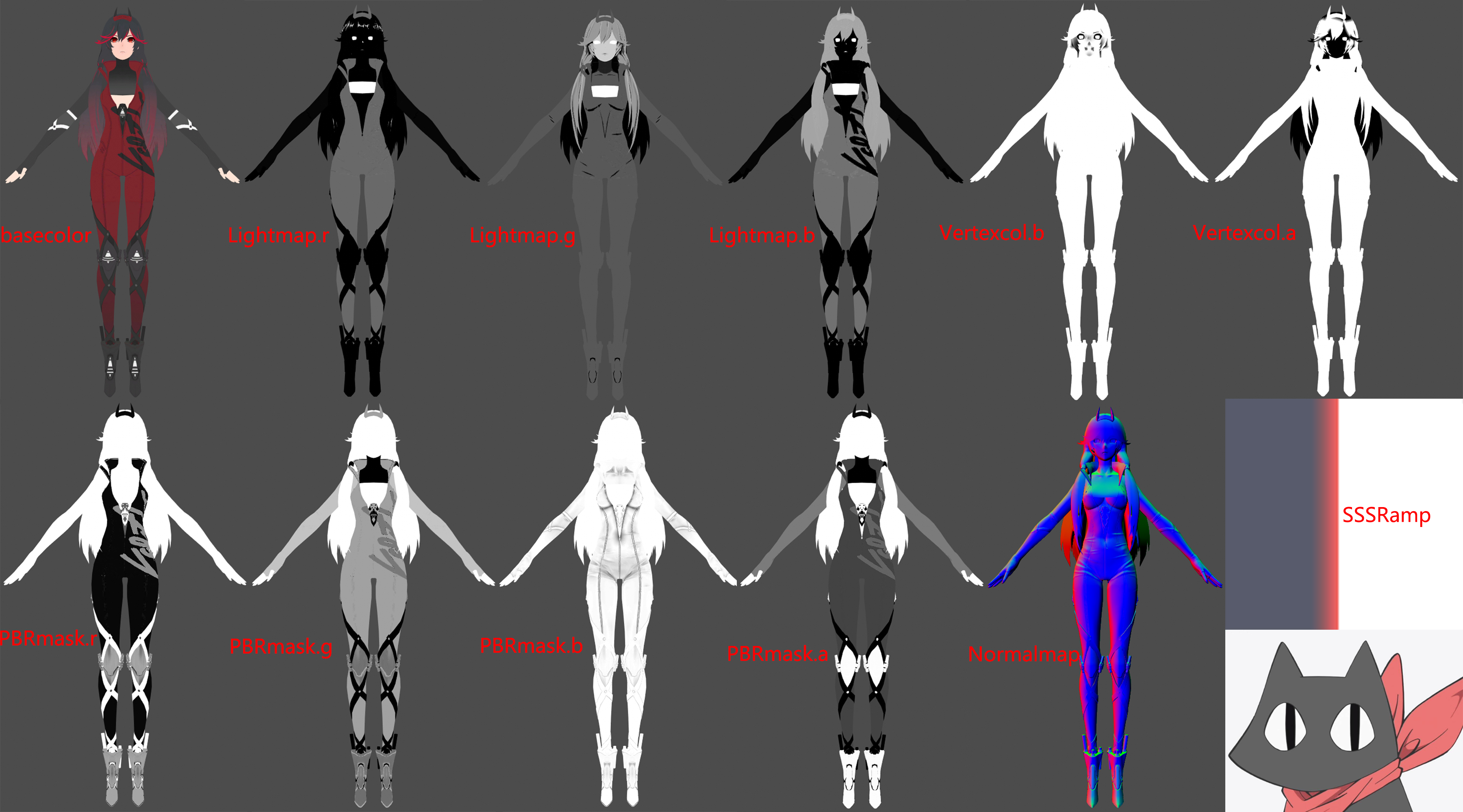
LightMap.r :Ramp偏移值,值越⼤的区域 越容易”感光”(在⼀个特定的⾓度,偏移光照明暗)
LightMap.g :固有阴影AO ShadowAOMask
LightMap.b :SpecularMask决定是否使用PBR
VertexColor.b :控制面部与头发描边
VertexColor.a :控制面部与头发描边粗细
PBRmask.r:Metallic 金属度
PBRmask.g:Smoothness 光滑度 (1.0 - 粗糙度)
PBRmask.b:AO 用于遮蔽高光
PBRmask.a:用于高光判断PBR倾向 lerp进行混合
Ramp:模拟皮肤SSS
Normal:做PBR的光影表现
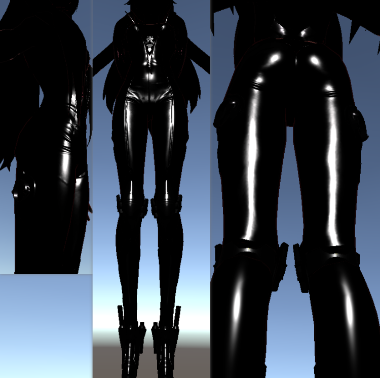
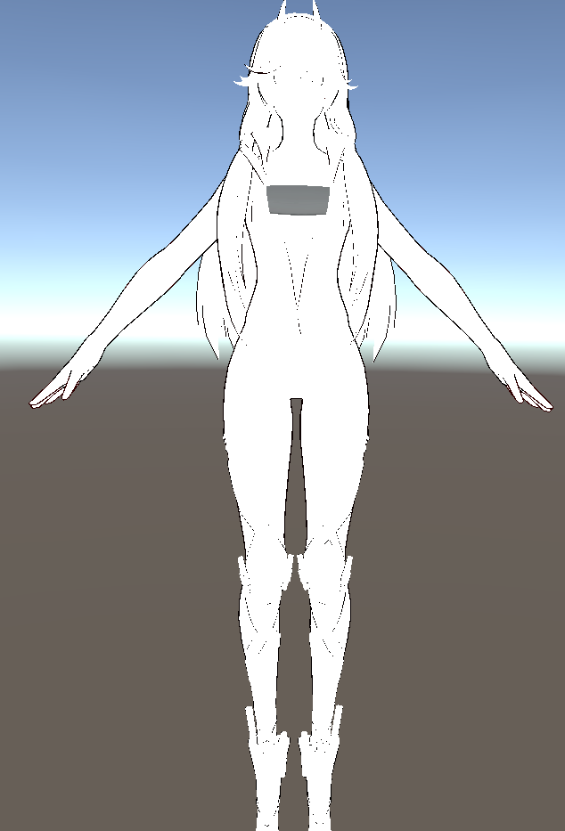
角色shader还原
漫反射
学到知乎上的一个方法“窗函数”相较于**step(_Threshold, Halflamber)**的过渡时硬边缘,可以在过渡时产生软边缘。如下图
1
2
3
4
5
6
7
8
9
10
11
12
13
14
|
float sigmoid(float x, float center, float sharp)
{
float s;
s = 1 / (1 + pow(100000, (-3 * sharp * (x - center))));
return s;
}
float3 BaseCol = tex2D(_BaseMap, i.uv).rgb;
float3 BaseColDark = _ShadowColor * BaseCol;
float halfLambert = NL * 0.5 + 0.5;
float HLightSig = sigmoid(NL + LightRampAdd + _LightRampOffset, _DividLineH, _BoundSharp);
float IsBrightSide = HLightSig * 1.0;
float3 diffuse = lerp(BaseColDark * _DarkIntensity, BaseCol * _BrightIntensity, IsBrightSide);
|
对于头发、面部、以及皮肤区域的Diffuse我们分开进行处理,面部与皮肤区域需要加上Ramp图做SSS效果。分别构造UV采样两张Ramp图。
1
2
3
4
| float2 UV_FaceRamp = float2(halfLambert + LightRampAdd + _FaceRampOffset*0.1, 0.5);
float2 UV_BodyRamp = float2(halfLambert + LightRampAdd + _BodyRampOffset*0.1, 0.5);
float3 Face_Ramp = tex2D(_FaceRampMap, UV_FaceRamp);
float3 Body_Ramp = tex2D(_BodyRampMap, UV_BodyRamp);
|
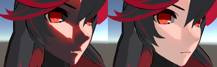
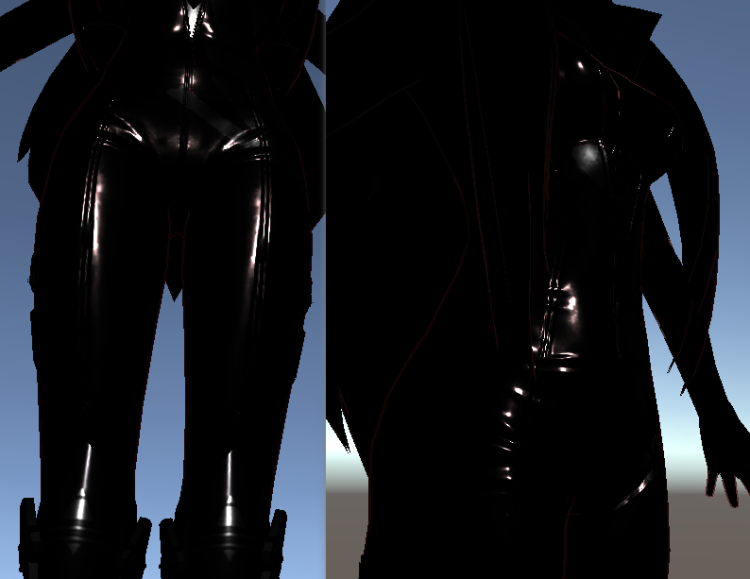
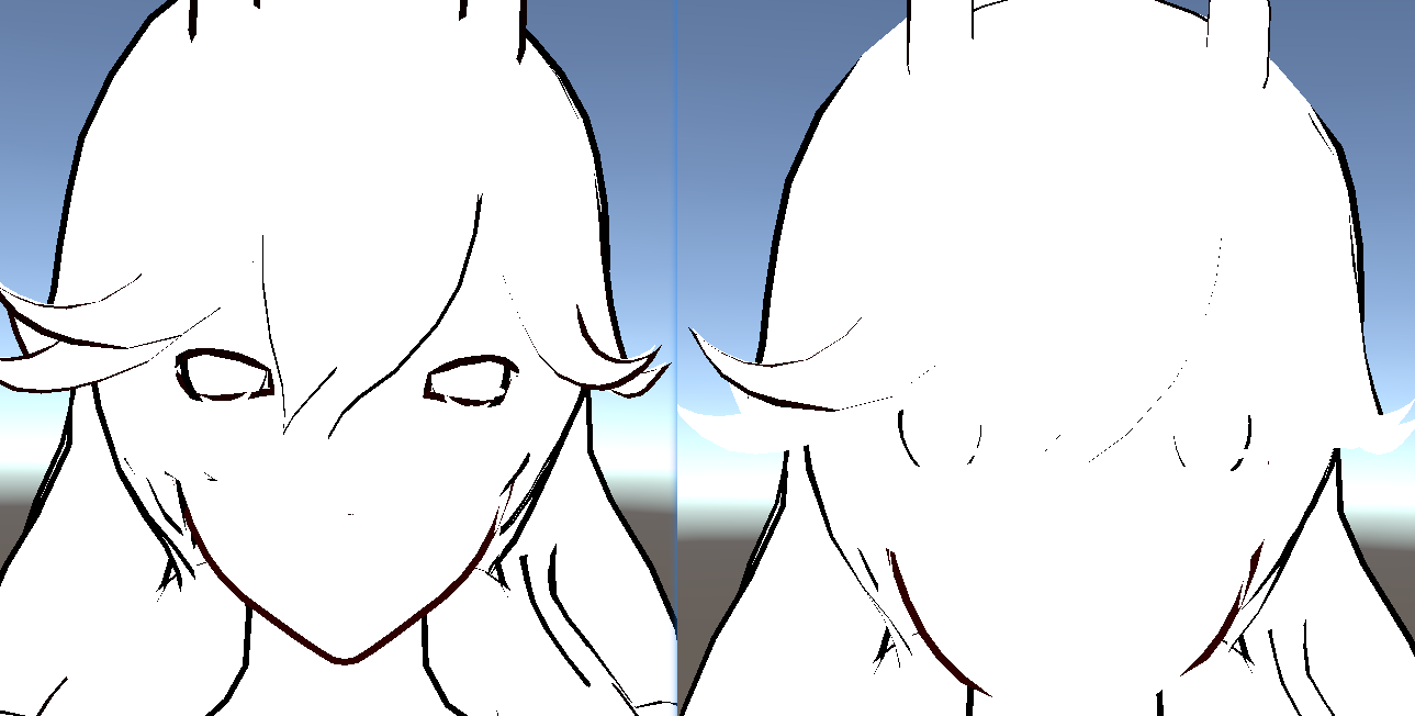
可以看到左边我们采样出来的结果不是很好,于是我们将basecolor与Ramp进行lerp得到右图中的效果,看起来相对顺眼了很多。对于皮肤我们也是一样的做法。
1
2
3
4
5
| diffuse *= Face_Ramp;
diffuse = lerp(diffuse, BaseCol,0.8);
diffuse *= Body_Ramp;
diffuse = lerp(diffuse, BaseCol,0.8);
|
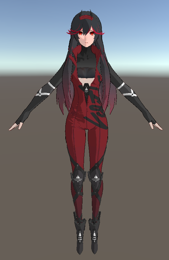
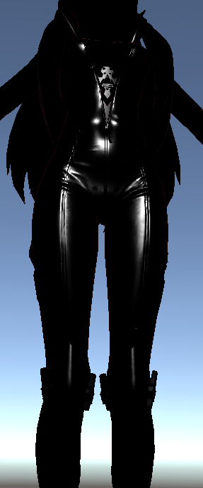
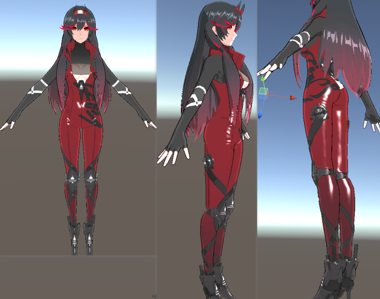
完整Diffuse效果
PBR高光
标准的PBR高光,通过D、F、G三项进行计算
1
2
3
4
5
6
7
8
| float3 F0 = lerp(0.04, BaseCol, Metallic);
float D = D_DistributionGGX(N, H, Roughness);
float3 F = F_FrenelSchlick(NV, F0);
float G = G_GeometrySmith(N, V, L, Roughness);
float3 nominator = D*F*G;
float denominator = max(0.001, 4*(NV*NL));
float3 PBRSpecular = nominator / denominator;
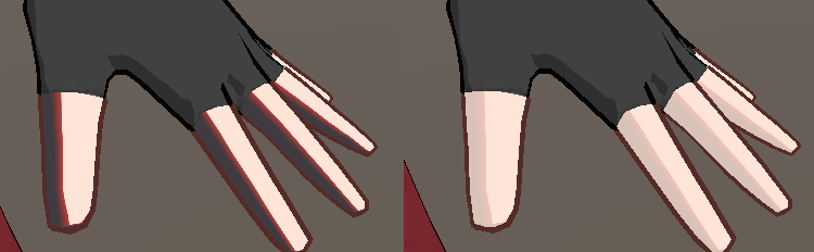
PBRSpecular *= AO * _PBRSpecularIntensity * (1.0 - Metallic);
|
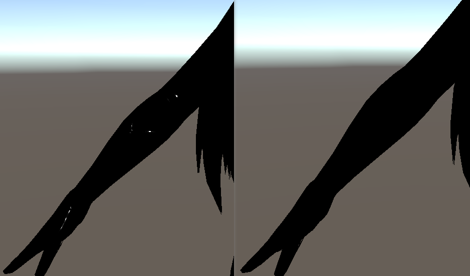
乘以(1.0 - Metallic)是为了去除手臂部分的高光。因为通过观察游戏,可以知道手臂部分是不带有高光的。
BlinnPhong高光
做法其实差不多。
1
2
| float3 BlinnSpecular = pow(saturate(NH), _SpecularExp) * _SpecularIntensity * (1.0 - Metallic);
BlinnSpecular = max(0.0, BlinnSpecular);
|
最后我们依据PBRmask.r进行对两种高光进行混合。
1
| specular = lerp(BlinnSpecular, PBRSpecular, PBRMask);
|
边缘光
相较于传统的NV*Lambert边缘光,这次使用了屏幕空间边缘光,基于相机深度进行偏移一定像素后用原深度减去偏移后的深度就能得到边缘光部分。
先在相机上挂载脚本,设置摄像机渲染深度,并在编辑界面显示。
1
2
3
4
5
6
7
8
9
10
11
12
13
14
15
16
17
18
19
20
21
22
23
24
25
26
27
28
29
30
31
32
33
34
35
| using System.Collections;
using System.Collections.Generic;
using UnityEngine;
[ExecuteInEditMode]
public class MainCameraDepth : MonoBehaviour
{
public Material mat;
public int width = 512;
public int height = 512;
private Camera cam;
private RenderTexture rt;
private int image_id = 0;
void Start()
{
cam = GetComponent<Camera>();
cam.depthTextureMode = DepthTextureMode.Depth;
}
void OnRenderImage(RenderTexture source, RenderTexture destination)
{
Graphics.Blit(source, destination, mat);
}
void Update()
{
}
}
|
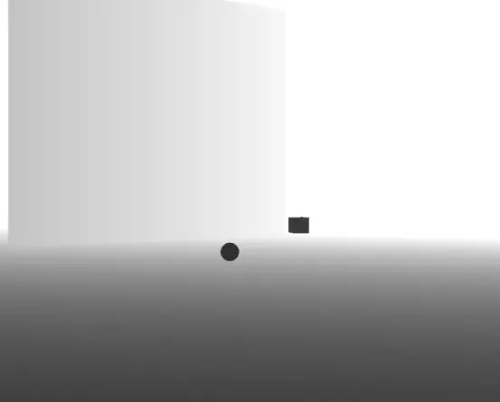
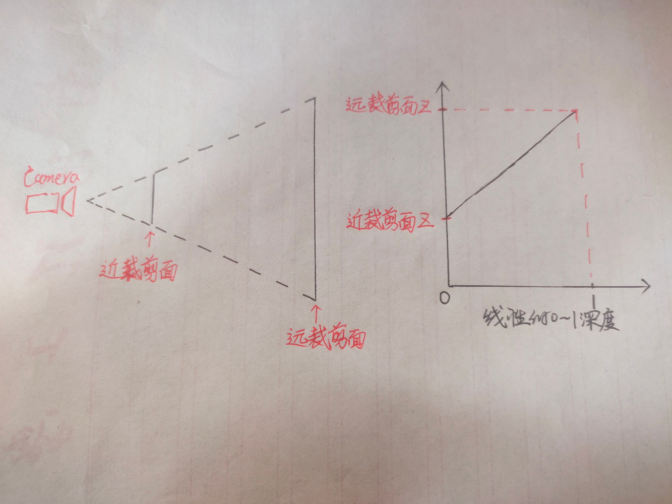
这张图就是对场景的深度纹理进行线性化后得到的图像,关于为什么要进行线性的变换,涉及到裁剪变换的一些知识,有兴趣的可以去看看乐乐姐的入门精要的相关部分,讲的很清楚。我们只需要知道直接采样深度纹理得到的并不是线性的深度。线性的深度应该是近裁剪面到远裁剪面之间的所有的点的Z值都和0到1有线性关系,如果物体深度为0.5那么其距离摄像机距离一定是在近裁剪面和远裁剪面的正中间。
深度图上距离摄像机近的物体呈现黑色,数值接近0,远的物体呈现白色,接近1,我们要利用这张图达到一种边缘检测的效果,可以想象一下,对场景中的球上的所有片元,向屏幕的左或右方向探索一定距离,再采样一个深度,用新采样的深度减去原本的深度,超过某个阈值则视为边缘。
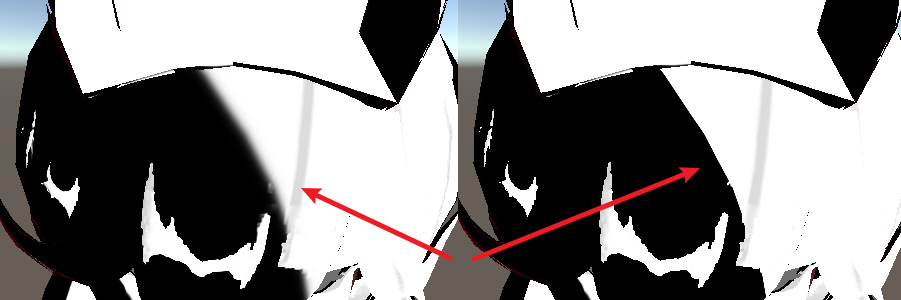
用图片解释一下这个过程:
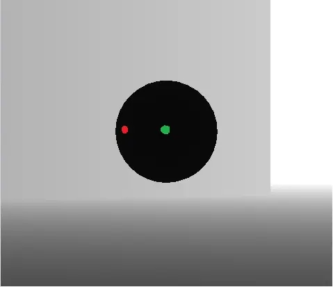
这张图中,红色是片元1,绿色是片元2,简称为F1,F2。注意是片元,不是顶点。片元是屏幕空间的一个单位。
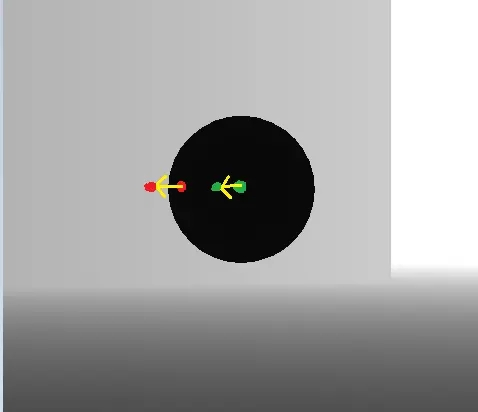
对于F1,F2,分别相对屏幕向左移动相同的距离,到达一个新的位置,采样这个位置的深度。
F1,F2原本都为黑色,深度都很小,都把他们假设为0,向左探索一段距离后采样的另两个深度中,F1采样到的新深度为灰色,就假设是0.8吧,F2采样到的依然是一个黑色0。
那么对于F1,F2,分别将偏移后采样到的深度与自身的深度相减,得到的结果一个是0.8一个是0,我们就让差距大于0.5的片元为呈现边缘光,那么F1为边缘光部分F2为无边缘光的部分。这只是两个片元,可以自行脑补球上所有片元都进行这样的计算得到的效果。
代码如下:
1
2
3
4
5
6
7
8
9
10
11
12
13
14
15
16
17
18
19
20
21
22
23
24
25
26
27
28
29
30
31
32
33
34
35
36
37
38
39
40
41
| struct v2f
{
float clipW :TEXCOORD1;
};
v2f vert (appdata_full v)
{
v2f o;
o.vertex = UnityObjectToClipPos(v.vertex);
o.clipW = o.vertex.w ;
return o;
}
float2 screenParams01 = float2(i.pos.x/_ScreenParams.x, i.pos.y/_ScreenParams.y);
float2 offectSamplePos1 = screenParams01 - float2(_RimOffect/i.clipW,0);
float offcetDepth1 = SAMPLE_DEPTH_TEXTURE(_CameraDepthTexture, offectSamplePos1);
float trueDepth = SAMPLE_DEPTH_TEXTURE(_CameraDepthTexture, screenParams01);
float linear01EyeOffectDepth1 = Linear01Depth(offcetDepth1);
float linear01EyeTrueDepth = Linear01Depth(trueDepth);
float depthDiffer1 = linear01EyeOffectDepth1 - linear01EyeTrueDepth;
float rimWidth1 = step(_RimThreshold, depthDiffer1);
float2 offectSamplePos2 = screenParams01 + float2(_RimOffect/i.clipW,0);
float offcetDepth2 = SAMPLE_DEPTH_TEXTURE(_CameraDepthTexture, offectSamplePos2);
float linear01EyeOffectDepth2 = Linear01Depth(offcetDepth2);
float depthDiffer2 = linear01EyeOffectDepth2 - linear01EyeTrueDepth;
float rimWidth2 = step(_RimThreshold, depthDiffer2);
float2 offectSamplePos3 = screenParams01 + float2(0, _RimOffect/i.clipW);
float offcetDepth3 = SAMPLE_DEPTH_TEXTURE(_CameraDepthTexture, offectSamplePos3);
float linear01EyeOffectDepth3 = Linear01Depth(offcetDepth3);
float depthDiffer3 = linear01EyeOffectDepth3 - linear01EyeTrueDepth;
float rimWidth3 = step(_RimThreshold, depthDiffer3);
float2 offectSamplePos4 = screenParams01 - float2(0, _RimOffect/i.clipW);
float offcetDepth4 = SAMPLE_DEPTH_TEXTURE(_CameraDepthTexture, offectSamplePos4);
float linear01EyeOffectDepth4 = Linear01Depth(offcetDepth4);
float depthDiffer4 = linear01EyeOffectDepth4 - linear01EyeTrueDepth;
float rimWidth4 = step(_RimThreshold, depthDiffer4);
float3 RimLight = max((rimWidth1 + rimWidth2), (rimWidth3 + rimWidth4)) * _RimColor * BaseCol * 0.3;
|
clipW,它决定了我们的边缘光是否有透视效果。这涉及裁剪空间的知识,有点复杂不多赘述,简单来说就是,我们要让屏幕空间的偏移有近大远小,也就是透视的效果,就要让距离摄像机远的顶点除以某个与距离有关的权值,使其缩小。
视锥体及里边的顶点经过P变换后变为一个正四棱锥,长下边这样,我们在顶点着色器里写的
o.vertex = UnityObjectToClipPos(v.vertex);
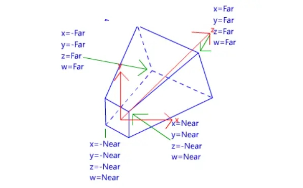
看图可知,这个空间里,坐标原点在四棱锥里面,而w代替z成为了真正的距离摄像机的距离,我们要达到近大远小的目的,就将顶点都除以顶点距离摄像机的距离。看图可知在这个空间里这个距离就是顶点的W分量。将这个四棱锥里所有的顶点都除以他的W分量后,会得到一个111大小的正方体,这个正方体中,原先在近裁剪面的顶点的xyz分量还会保持较大的数值,而远处的顶点的xyz分量则会因除以更大的w值而变得较小,从而达到近大远小的效果,这一步在渲染管线里叫透视除法。
顶点的透视除法由unity自动帮我们完成,在顶点着色器和片元着色器之间,所以顶点的近大远小我们不需要怎么关心,但是如果想让其他的一些效果也有近大远小,则要手动除以W分量。
已知顶点着色器和片元着色器之间将发生透视除法,透视除法之后的顶点的w分量都为1,所以我们要在透视除法之前也就是顶点着色器里记录下w,存入v2f,并在片元着色器里使用。
1
| float2 screenParams01 = float2(i.pos.x/_ScreenParams.x,i.pos.y/_ScreenParams.y);
|
i.pos是片元的屏幕像素坐标,要把我的1920*1080的屏幕上的坐标映射到0到1,显然是对坐标的x和y分别除以1920和1080。_ScreenParams的xy分量记录的就是屏幕的像素宽度和高度,这很关键,因为对各种纹理的采样实际上是采样0到1的范围而不是具体的像素。 现在我们得到了screenParams01这个0-1范围内顶点的屏幕空间的坐标。
1
| float2 offectSamplePos = screenParams01-float2(_RimOffect/i.clipW,0);
|
对这个坐标,对x减去我们设置的偏移量,偏移量为_RimOffect/i.clipW,这里除w就是手动的透视除法。在视口空间我们的屏幕左下角为(0,0),右上角为(1,1),x减小是向左偏移。
1
2
3
4
| float offcetDepth = SAMPLE_DEPTH_TEXTURE(_CameraDepthTexture, offectSamplePos);
float trueDepth = SAMPLE_DEPTH_TEXTURE(_CameraDepthTexture, screenParams01);
float linear01EyeOffectDepth = Linear01Depth(offcetDepth);
float linear01EyeTrueDepth = Linear01Depth(trueDepth);
|
对原本的位置和偏转后的位置采样深度图,并将采样得到的值变为线性深度。
这里可以看到我们采样_CameraDepthTexture这个深度纹理的时候用的就是我们上边的得到的x和y范围为0到1的视口空间坐标。
1
2
3
| float depthDiffer = linear01EyeOffectDepth-linear01EyeTrueDepth;
float rimWidth = step(_Threshold,depthDiffer);
float4 col = float4(rimWidth.xxx,1);
|
两个深度值相减,超过设定的阈值rimWidth为1,没超过则rimWidth为0。
修该一下代码得到四边都是边缘光的效果,我这里乘上了basecolor。
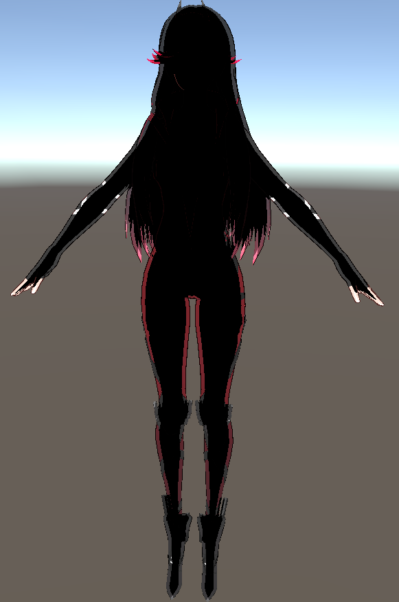
描边
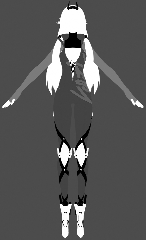
在面部使用了顶点色的b通道和a通道控制描边。
1
2
3
4
5
6
7
8
9
10
11
12
13
14
15
16
17
18
19
20
21
22
23
24
25
26
27
28
29
30
31
32
33
34
35
36
37
38
39
40
41
42
43
44
45
46
47
48
49
50
51
52
53
54
55
| Pass
{
Cull Front
CGPROGRAM
#pragma vertex vert
#pragma fragment frag
#include "UnityCG.cginc"
struct appdata
{
float4 vertex : POSITION;
float2 uv0 : TEXCOORD0;
float3 normal : NORMAL;
float4 color : COLOR;
};
struct v2f
{
float4 pos : SV_POSITION;
float2 uv : TEXCOORD0;
float4 vertexCol : TEXCOORD1;
};
sampler2D _BaseMap;
float _OutLineWidth;
float _OutLineBias;
float4 _OutLineColor;
v2f vert (appdata v)
{
v2f o;
float3 posVS = UnityObjectToViewPos(v.vertex).xyz;
float3 ndirWS = UnityObjectToWorldNormal(v.normal);
float3 ndirVS = mul((float3x3)UNITY_MATRIX_V, ndirWS);
ndirVS.z = _OutLineBias * (1.0 - v.color.b);
posVS += ndirVS * _OutLineWidth * 0.001 * v.color.a;
o.pos = mul(UNITY_MATRIX_P, float4(posVS, 1.0));
o.uv = v.uv0;
o.vertexCol = v.color;
return o;
}
float4 frag (v2f i) : SV_Target
{
float3 BaseCol = tex2D(_BaseMap,i.uv).rgb;
float maxComponent = max(max(BaseCol.r, BaseCol.g), BaseCol.b) - 0.004;
float saturatedCol = step(maxComponent.rrr, BaseCol) * BaseCol;
saturatedCol = lerp(BaseCol, saturatedCol, 0.6);
float3 outlineCol = 0.5 * saturatedCol * BaseCol * _OutLineColor;
return float4(outlineCol, 1.0);
}
ENDCG
}
|
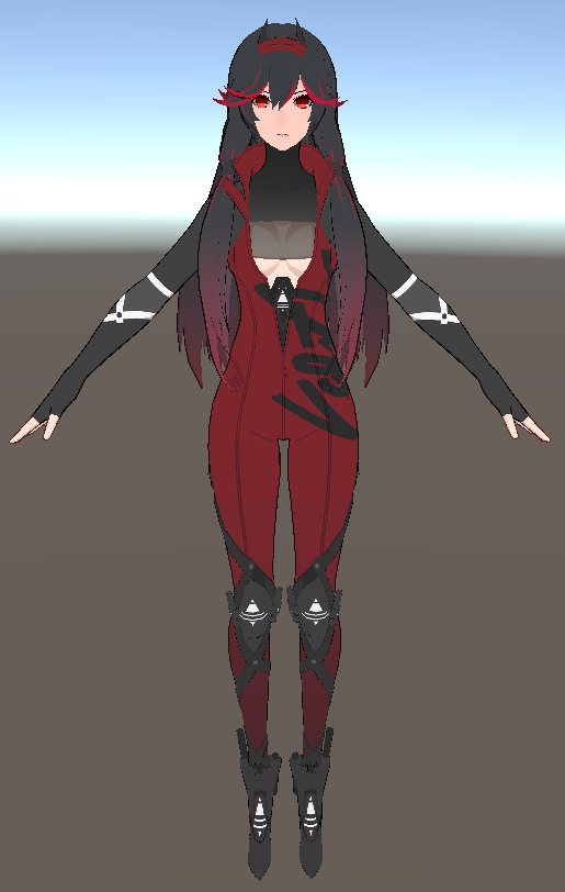
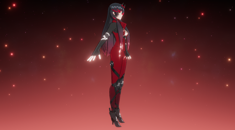
最后效果
加一点后处理
写的时间比较久远,留作纪念吧_(:з」∠)_